


Excerpt:
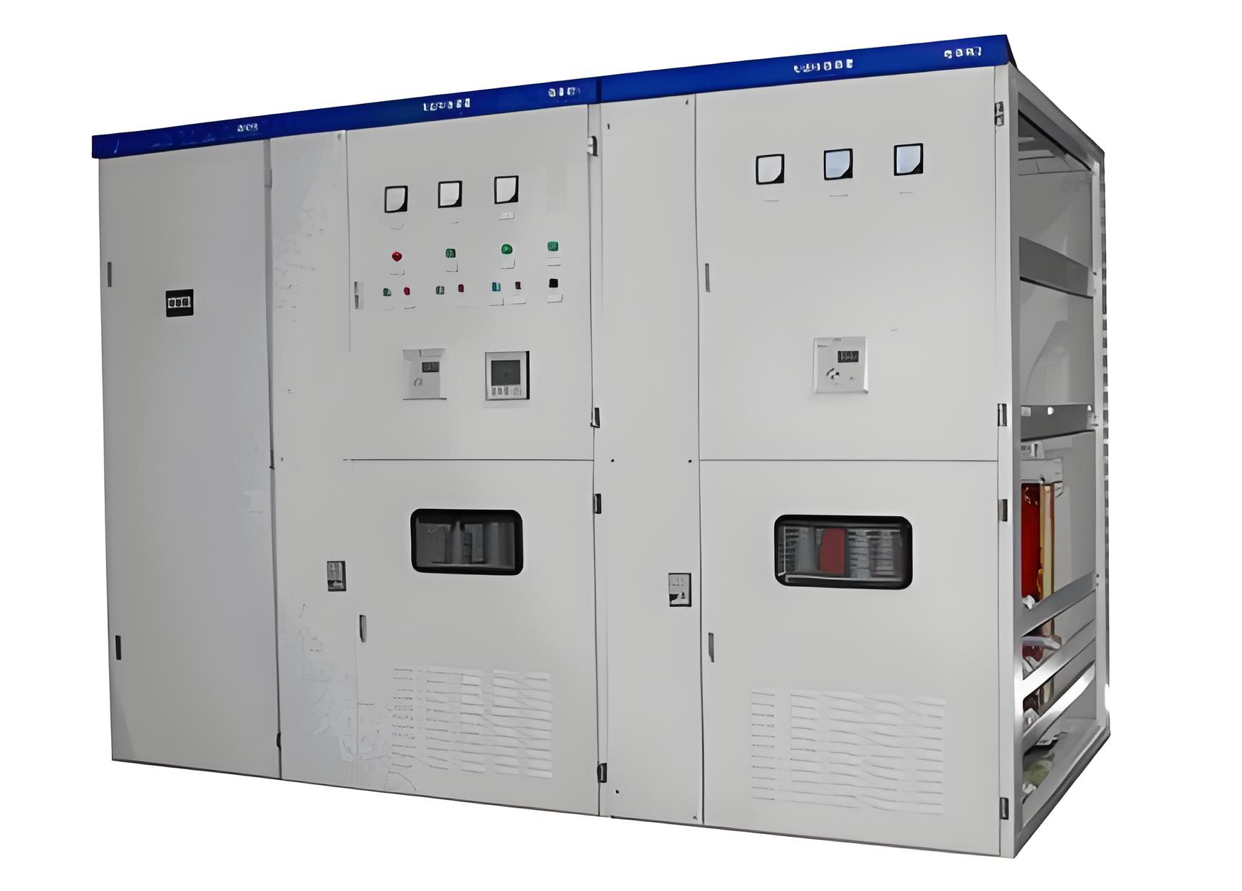
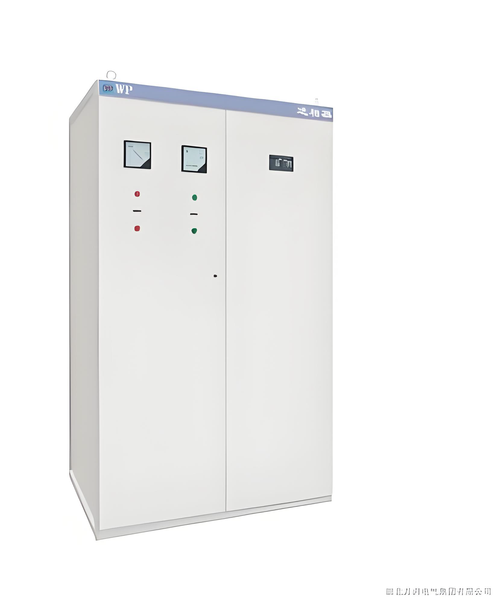
The high voltage reactive power compensation cabinet is designed to improve power factor, reduce energy losses, and enhance the efficiency of high-voltage electrical systems. It ensures stable and reliable operation in industrial plants, power stations, and large-scale facilities.
High-Voltage Reactive Power Compensation Cabinet: Efficient Energy-Saving Solution for Power Quality Enhancement
01 Product Overview
The High-Voltage Reactive Power Compensation Cabinet is a key device for 6kV/10kV and above power systems, designed to reduce electricity costs and improve grid power quality. By connecting parallel capacitor banks, it increases system power factor, reduces line losses, and lowers energy costs.
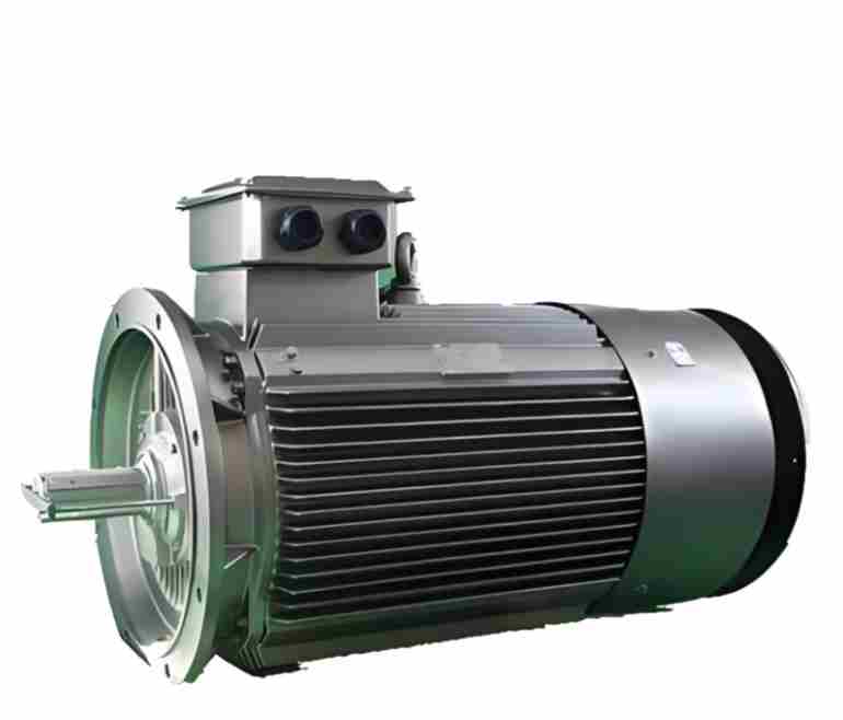
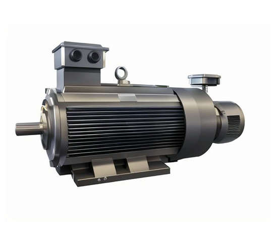
Widely applied in metallurgy, mining, building materials, petrochemicals, and heavy machinery, it supports local reactive power compensation for high-power high-voltage motors and centralized compensation in distribution systems, effectively raising the power factor from 0.75 to over 0.95 and preventing utility penalties for low power factor.
02 Working Principle & Technical Features
1. Intelligent Working Principle
The cabinet operates based on parallel capacitor compensation. Most industrial loads are inductive (e.g., asynchronous motors), drawing significant reactive power. This creates a phase difference between voltage and current, resulting in low power factor.
By adding parallel capacitors, capacitive reactive power offsets the inductive reactive power, reducing phase difference, improving power factor, lowering transformer and line losses, and enhancing grid quality.
2. Automatic Control Mechanism
Modern cabinets use smart controllers to monitor system voltage, reactive power, and power factor in real time. When reactive power exceeds preset thresholds, the controller sends signals to high-voltage vacuum switches to connect capacitor banks automatically.
When reactive power drops below set levels, the controller disconnects capacitor banks. The process is fully automatic, maintaining a stable power factor of 0.95–0.99 without overcompensation.
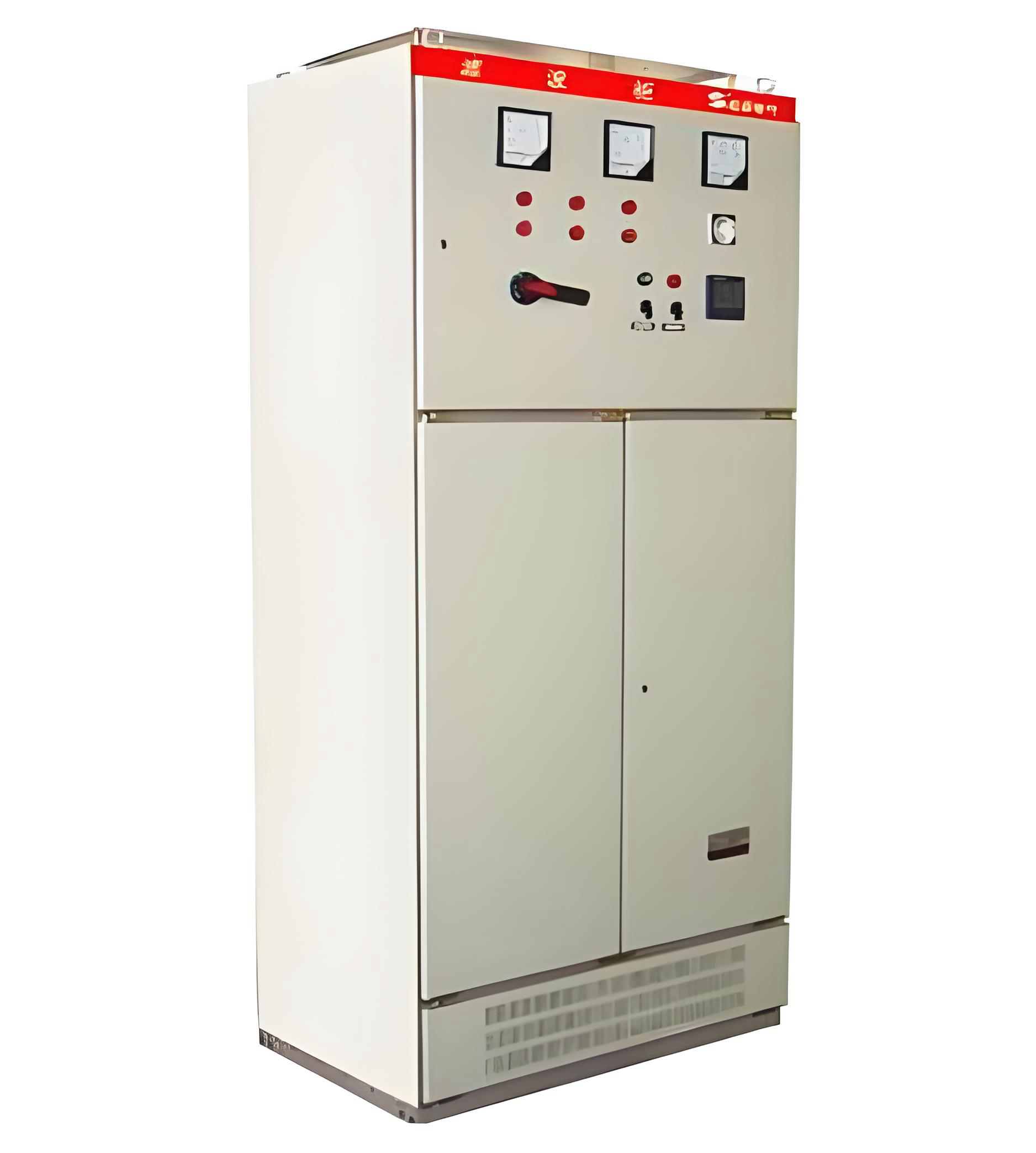
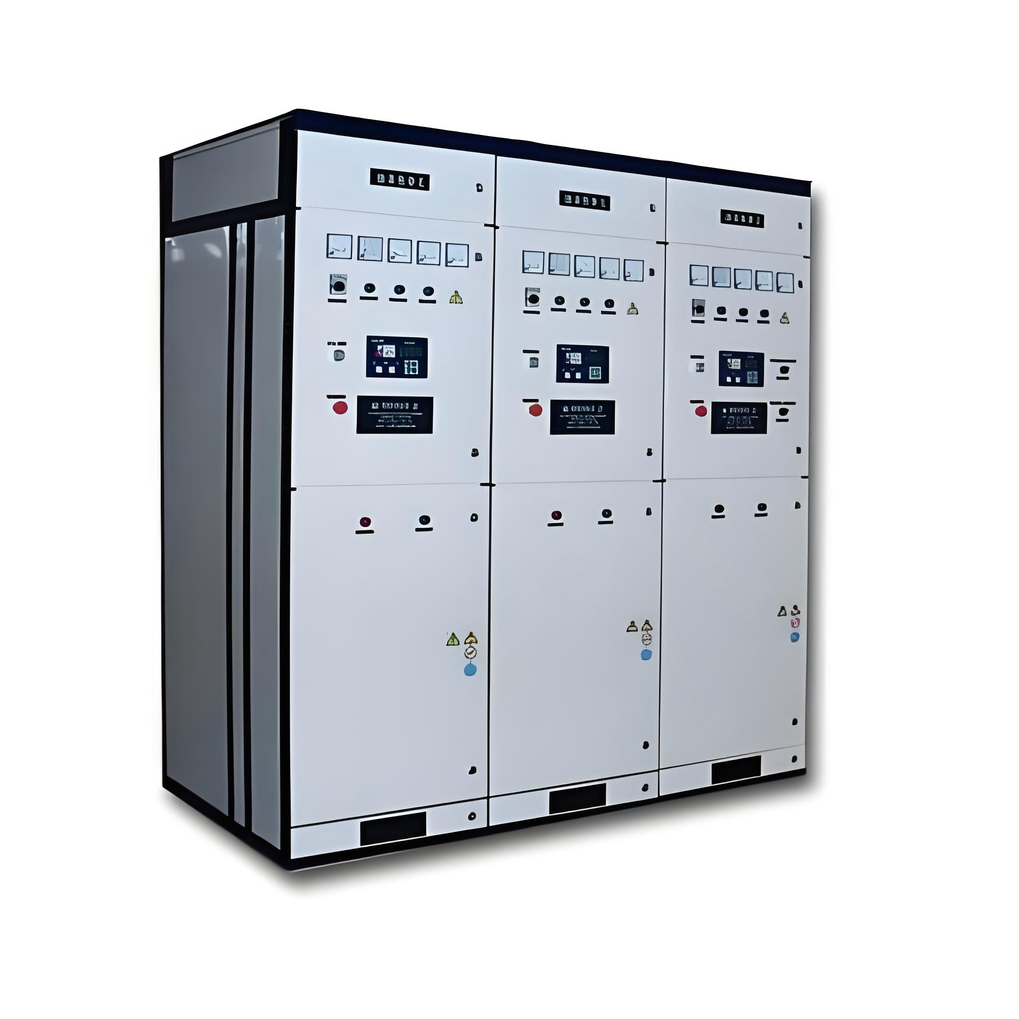
03 Core Structure & Components
1. Key Components
- Parallel Capacitors: Vacuum-deposited metallized polypropylene film capacitors; compact, high capacity, low loss, and lightweight, with internal losses only 20% of typical oil-filled capacitors.
- Series Reactors: Limit inrush current and suppress harmonics. Typical reactance: XL = 0.1–1%XC for inrush limitation; 5–6%XC for 5th harmonic suppression; 12–13%XC for 3rd harmonic suppression.
- Switching Devices: High-voltage vacuum contactors or breakers for fast, reliable capacitor switching.
- Smart Controller: Microprocessor-based, implementing advanced algorithms for dynamic reactive power compensation.
2. Protection & Safety Systems
- Protection Components: High-voltage fuses for short-circuit protection; zinc oxide arresters for overvoltage during switching.
- Discharge Devices: Discharge capacitors within 5 seconds to below 50V after disconnecting to ensure safety.
- Monitoring Systems: Includes three-phase ammeters, voltmeters, and status indicators for real-time parameter monitoring.
04 Performance Features & Advantages
1. Energy Efficiency
- Power Factor Improvement: Raises grid power factor from 0.75 to above 0.98.
- Reduced Energy Losses: Line current decreases 10–20%, reducing transmission losses.
- Enhanced Equipment Utilization: Improves transformer loading and motor efficiency.
2. Intelligent Control
- Multiple Switching Strategies: Supports cyclic, first-in-first-out, and time-delay switching for even capacitor utilization.
- Voltage-Priority Operation: Automatically adjusts switching to maintain voltage quality.
- Remote Monitoring: RS-232/RS-485/infrared interfaces for local and remote control.
3. Safety & Reliability
- Comprehensive Protection: Overvoltage, undervoltage, overcurrent, zero-sequence, and instantaneous protection.
- Intelligent Diagnostics: Audible/visual alarms indicate faults and lockout points.
- Automatic Temperature Control: Monitors internal temperature and activates exhaust fans as needed.
05 Technical Specifications
| Parameter | Specification |
|---|---|
| Rated Voltage | 6kV / 10kV |
| Maximum Operating Voltage | 7.2kV / 12kV |
| Rated Frequency | 50Hz |
| Capacitor Bank Capacity | 300–2400 kVar per bank, customizable |
| Power Factor Improvement | From 0.75 to 0.95–0.98 |
| Operating Temperature | -25℃ ~ +45℃ |
| Protection Class | Indoor installation, cabinet-dependent |
| Capacitor Tolerance | ±5% to +10% of rated value |
06 Application Areas
1. Heavy Industry
- Metallurgy: Rolling mills, electric arc furnaces, large reactive load compensation.
- Mining: Hoists, crushers, conveyors, improving power quality.
- Building Materials: Cement ball mills, fans, increasing power factor.
2. Energy-Intensive Industries
- Petrochemicals: Compressors and pumps for localized compensation.
- Power Systems: Substations and distribution networks for centralized compensation.
- Water Treatment: Large pump motors, reducing line losses.
3. Special Environments
- High Harmonics: Configured reactors suppress harmonic amplification.
- Voltage Fluctuations: Rapid switching stabilizes grid voltage.
- Space-Constrained Sites: Compact design for limited installation space.
07 Selection & Installation Guide
Selection Considerations
- Load Analysis: Inductive load ratio, operating hours, and variability.
- Existing Power Factor: Measure and determine required compensation.
- Harmonics: Decide if filter reactors are necessary.
- Installation Environment: Temperature, humidity, altitude, protection class.
Capacity Determination
- Power Factor Method: Calculate based on existing and target power factor.
- Reactive Power Demand: Determine from system load curve.
- Empirical Factor: Estimate 20–40% of transformer capacity.
Installation Requirements
- Indoor Installation: Free of harmful gases, conductive or explosive dust.
- Environmental Limits: -25℃ to +45℃, relative humidity <90%.
- Altitude: ≤ 2000m (special design above 2000m).
- Ventilation: Ensure sufficient airflow; install fans if necessary.
08 Benefits Analysis
Direct Economic Benefits
- Electricity Savings: Avoid penalties, enjoy incentives.
- Reduced Line Losses: 10–20% reduction in current and losses.
- Improved Equipment Utilization: Higher transformer loading, delaying expansion costs.
Comprehensive Benefits
- Improved Power Quality: Reduced voltage fluctuations, enhanced reliability.
- Extended Equipment Life: Minimizes reactive current impact on motors and transformers.
- Increased Production Efficiency: Stable voltage reduces production interruptions.
09 Conclusion
The High-Voltage Reactive Power Compensation Cabinet is a core solution for industrial power quality management, providing efficient power factor correction, energy savings, and grid stability.
For industrial enterprises seeking energy efficiency and operational optimization, choosing the right high-voltage reactive power compensation cabinet is a strategic investment. Consulting professionals ensures maximum economic and technical benefits tailored to specific electrical systems.


 Shaanxi Public Network Security No. 41032502000206


